VT2848
General-Purpose Digital I/O Module
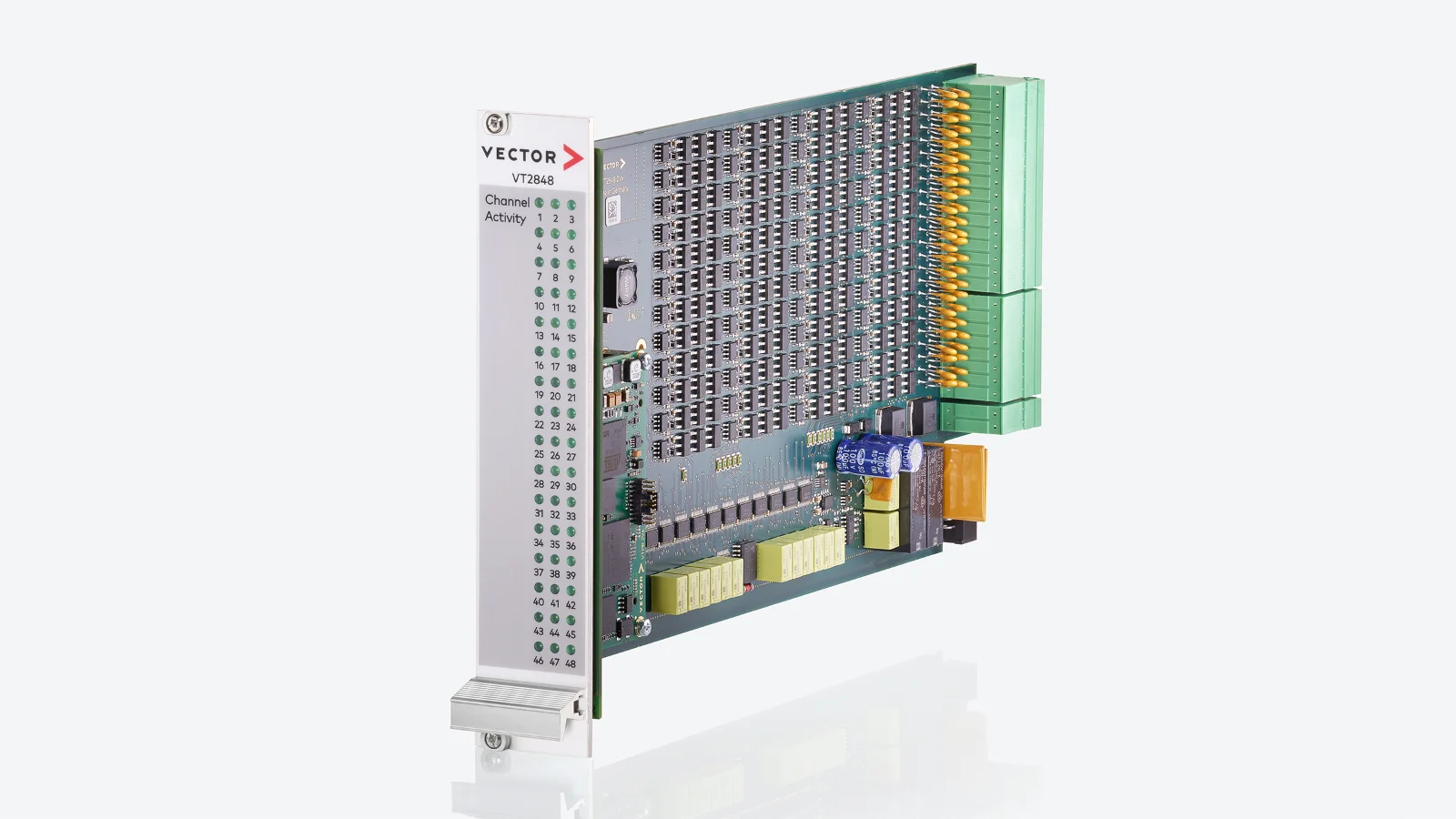
The module VT2848 provides 48 inputs or outputs for digital signals. They may be connected directly to the inputs or outputs of an ECU. Also, other digital signals can be measured or controlled using this module, e.g. to control additional parts of a test bench.
This module is also available as a variant (VT2848 FPGA) with user programmable FPGA.
Characteristics
Functions for Each Column
- Channel individually configurable as input or output channel
- Sampling of digital input signals with configurable threshold
- Determination of frequency and duty cycle of PWM signals (on 16 channels)
- Outputs use transistors to allow endurance tests
- Autonomous output of a bit stream loaded into module
3 modes for digital output:
- Push-pull operation against Vbatt or Vext
- Low-side switch
- High-side switch against Vbatt or Vext
- Generation of a PWM signal (on 16 channels)
Technical Data
| VT2848 | ||
| Input of digital signals | ||
| Input voltage | 0 V … 60 V | |
| Input impedance | Approx. 200 kΩ | |
| Threshold | 0 … 40 V | |
| Hysteresis | Approx. 0.2 V | |
| Sampling interval | 50 µs | |
| PMW frequency (PWM measurement) | 20 mHz … 500 kHz | |
| Output of digital signals | ||
| Supply voltage Vbatt / Vext | 2 … 60 V | |
| Input current at Vbatt / Vext | Max. 7 A | |
| Output Low | ||
| – Output voltage (at -20 mA) | Max. 0.2 V | |
| – Output current | -200 … 0 mA | |
| Output High | ||
| – Output voltage (at 20 mA) | Min. Vbatt/Vext -0.9 V | |
| – Output current | 0 … 200 mA | |
| Length of bit stream | 2 … 4,096 Bit | |
| Output interval (at Vbatt / Vext ≤ 24 V) | 5 μs … 65 ms | |
| Frequency of generated PWM signal | ||
| – at Vbatt/ext ≤ 60V | 20 mHz … 10 kHz | |
| – at Vbatt/ext ≤ 12V | 20 mHz … 200 kHz | |
| Basic Data | ||
| Supply voltage (via backplane) | 12 V ±10% | |
| Power consumption | Typ. 5.8 W | |
| Temperature range | 0 … 55 °C | |
| Dimensions (L x W x H) | 300 x 173 x 36 mm | |
| Weight | Approx. 460 g | |
| Maintenance | ||
| Calibration recommended | every 12 months | |
| Accredited (pre/re) calibration according to | ISO/IEC 17025:2017 | |